Safety and quality according to the strictest standard
To determine the electrical safety of fluxes in soldering technology, the surface insulation resistance (SIR) must be measured. Specifically, the insulation resistance between adjacent conductors on the surface of a PCB is determined. This is done with the help of so-called SIR Tests: Under precisely defined test conditions, the SIR values of a live PCB are recorded over a defined period of time. The test result provides information on whether the flux used is electrically safe.
Tests according to IPC J-STD-004C
SIR Tests play an important role in both product development and product classification, because: If unsafe fluxes are used in soldering processes, they can cause short circuits on the PCBs. This can subsequently lead to production or machine failures or to defective end devices. "SIR Tests are an absolute must for soldering materials used in the electronics industry," explains Diana Merkwitz, SIR Test expert at Stannol. "However, it also depends on which standard is being tested." At Stannol, SIR Tests for its own products are carried out exclusively according to the current American guideline IPC J-STD-004C.
This characterises and classifies fluxes for leaded and lead-free solders and is currently considered one of the strictest standards worldwide. "Customers from the automotive industry, aerospace or medical technology in particular attach great importance to the fact that the fluxes used are electrically safe. Stannol tests its products according to this standard because the test conditions specified therein place particularly high demands on the tested products and thus on their safety," Merkwitz emphasises. If a flux is to be classified according to the aforementioned standard, the SIR Test is one of several tests that must be carried out for this purpose.
Climate Cabinet and Measuring Device

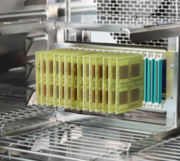
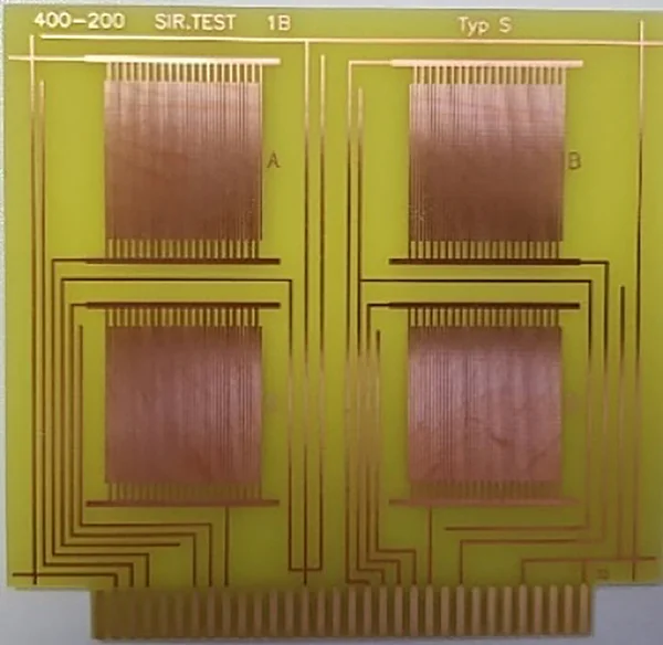
The standard exactly specifies the climatic conditions under which the tests take place and which conductor geometry must be used for this, i.e. which width and which distances the conductors must have, for example. In addition, parameters such as current strength and runtime of the test are precisely defined. The prepared test boards are attached to two test racks in the climate cabinet with edge connectors, linked to the external measuring device and supplied with current. The test boards are positioned in such a way that the prepared PCBs are parallel to the air flow. Temperature and humidity are then slowly increased via a ramp until the desired values are reached. The measuring device then records the SIR values of each individual comb on the PCBs at 20-minute intervals. "The recorded measurements can now be easily read out. It can be precisely traced for each test structure whether and when there was a drop in the required resistance."
High humidity as an endurance test

SIR measurements are complex: The tests have to be carefully prepared and carried out over a longer period of time. Diana Merkwitz: "The pure running time of a SIR test is one week. In addition, the PCBs have to be set up – they first have to be prepared with the flux or solder wire to be tested according to the particular specifications." The SIR tests according to IPC J-STD-004C create a kind of worst-case scenario: The prepared PCBs are exposed to current in a climate cabinet at 40 degrees Celsius and 90 percent relative humidity. "In contrast to the older -004A standard, here measurements are taken at a lower temperature, but at a higher humidity. That means it is colder, but at the same time more humid. In addition, the distances between the conductive tracks on the test structure are smaller according to standard -004C. Both are an absolute endurance test for the flux used," emphasises the expert.
Dendrites are knockout criteria

The standard also requires a resistance of at least 108 ohms, which must be maintained over a period of 168 hours. Here, too, the C standard is more strict: For this resistance must be reached after 24 hours at the latest and then maintained until the end of the test. For the previous version, it was sufficient if this resistance was only reached shortly before the end of the test. During the test, the resistance must not drop below 108 ohms – otherwise the test is considered as failed. The exception: the resistance only drops in certain places, for example because the PCB is contaminated by a fibre or because a bridge was formed by tin during soldering.
"We don't test in the Clean Room, but under real conditions. The material is used in the same way as in production. Therefore, such impurities are perfectly normal. If it can be clearly seen under the microscope that the resistance has only dropped due to contamination, this has no negative effect on the test result," the expert emphasises.
Under no circumstances should dendrites form during the test. Dendrites are shrub-like branches of copper that form between the conductive tracks and lead to a short circuit. "This is an absolute knock-out criterion: if dendrites form or the distance between the PCBs decreases by more than 20 per cent due to so-called electrochemical migration, the test is considered failed. The flux would then not be electrically safe."
Stricter than the norm requires

Stannol even goes beyond the required parameters of the standard in some areas. "The standard actually requires ten test combs for testing fluxes in solder wires. But we use a total of 16 combs. This not only results in a larger test field, but also in a plus in safety," explains Merkwitz. Stannol also sets tougher conditions for the SIR Tests of liquid fluxes – by voluntarily adding a complete test scenario. Because the standard only specifies two scenarios here: First, three PCBs (twelve combs) of the test boards must be sprayed with flux and the conductive tracks soldered. Secondly, three further PCBs must be treated with flux and run over the solder wave with the back of the PCB (upside-down). As a third scenario, additional PCBs are sprayed with flux at Stannol and merely dried at room temperature – without the influence of heat. Diana Merkwitz: "This is to simulate the process in a selective soldering system, where the flux is also not exposed to heat. We want to know how it behaves under these circumstances and whether it can still be used safely."
SIR Tests for customers
Stannol not only performs SIR Tests for its own products, but also offers the service to external companies. In particular, when it comes to the combination of different fluxes on a PCB, for example because different soldering processes with different soldering agents are used during assembly, a special SIR Test for precisely this combination can make sense. For this purpose, the customer sends ready-prepared PCBs to Stannol, which are then tested in the in-house laboratory in close collaboration. "We not only carry out the measurement, but also prepare a detailed report afterwards. If the test result is not satisfactory for the customer, we provide tips on request on how the processes can be changed so that the result is better, for example by choosing other compositions or combinations," explains Merkwitz.
Requirements for a SIR Test:
- wave soldering system (for separate fluxes)
- soldering iron (for flux in solder wires)
- printed circuit boards prepared according to standard specifications
- climate cabinet
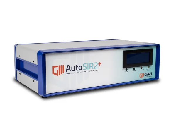
- SIR measuring device, e.g. AutoSIR 2+ from GEN3 Systems
Contact our Expert
Author